 Search
 Eng
Eng 
 English
 Español
 Português


Complete Guide to Automobile Brake Systems for Global Buyers
 2026.07.23
 Industry News
Content
- 1 What an Automobile Brake System Actually Does
- 2 Automotive Brake System Components Explained
- 3 How a Hydraulic Brake System Works
- 4 Comparing Disc and Drum Automotive Brake Systems
- 5 Brake System Demand Across Vehicle Segments
- 6 Brake Component Wear and Service Life Patterns
- 7 Choosing a Reliable Brake System Supplier and OEM Partner
- 8 OEM Automotive Brake System Manufacturing at Scale
- 9 Regional Vehicle Compatibility for Brake Parts
- 10 Maintenance Practices That Extend Brake System Life
- 11 Common Causes of Brake System Failure
- 12 Frequently Asked Questions About Automotive Brake Systems
- 12.1 Q1: What is an automobile brake system
- 12.2 Q2: How does a hydraulic brake system work
- 12.3 Q3: What are the four types of braking systems
- 12.4 Q4: What are the main parts of a brake system
- 12.5 Q5: How long do brake systems last
- 12.6 Q6: What causes brake failure
- 12.7 Q7: How do you maintain a brake system
- 12.8 Q8: What is the difference between ABS and conventional brakes
What an Automobile Brake System Actually Does
An automobile brake system converts the moving vehicle's kinetic energy into heat through controlled friction, slowing the wheels and bringing the vehicle to a stop or holding it in place on a grade. Every modern automotive brake system follows the same basic chain regardless of vehicle size or origin, a driver input at the pedal, a hydraulic or mechanical transfer of that input, and a friction interface at each wheel that resists rotation. Once this chain is understood, it becomes clear why brake system components need to be engineered and installed as a matched set rather than as separate, unrelated parts.
Four working principles govern almost every automotive brake system on the road, friction between a pad or shoe and a rotating surface, mechanical leverage at the pedal, hydraulic pressure multiplication through the fluid circuit, and heat dissipation away from the friction surfaces. A brake system that performs well in one of these areas but not the others tends to show up as a specific complaint, uneven pedal feel, fade on long descents, or noise under light braking. Buyers sourcing brake parts for resale or fleet use generally look at all four principles together rather than judging a single component on its own.
Automotive Brake System Components Explained
A complete set of brake system components spans the pedal assembly, the hydraulic circuit, and the friction assembly at each wheel. The table below groups the parts that commonly appear on passenger cars, light trucks, and crossover vehicles, along with their general location and the role each one plays inside the automotive brake system.
| Component | Typical Location | Primary Function |
|---|---|---|
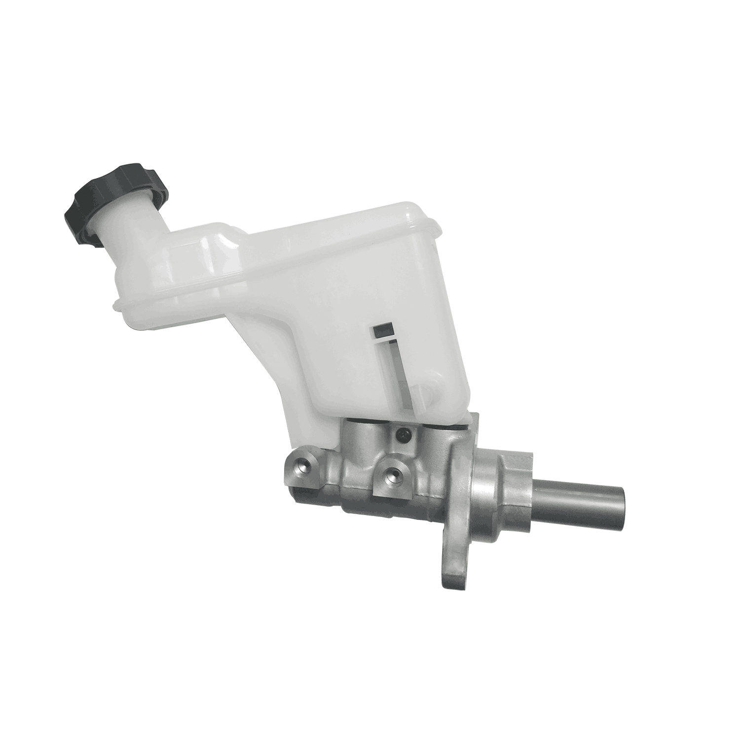
| Brake Master Cylinder | Firewall, pedal side | Turns pedal force into hydraulic pressure |
| Brake Booster | Between pedal and master cylinder | Amplifies driver pedal effort |
| Brake Lines and Hoses | Chassis and wheel wells | Carries pressurized fluid to each wheel |
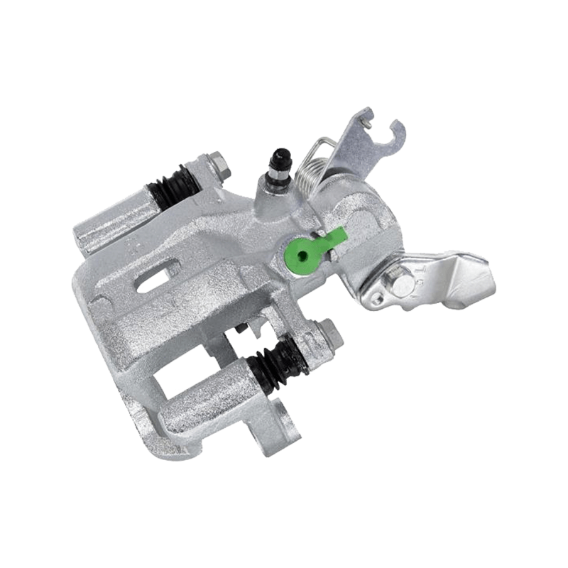
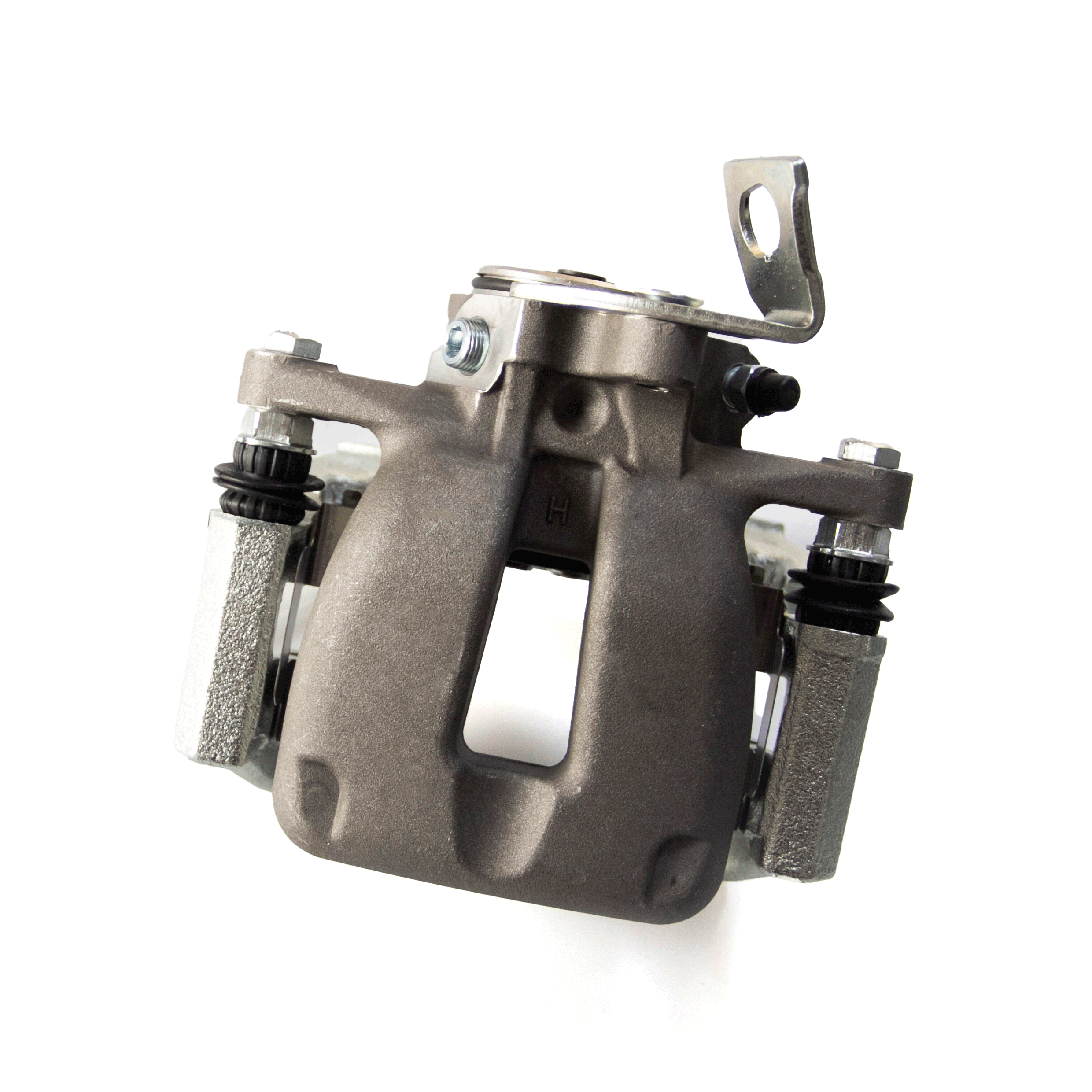
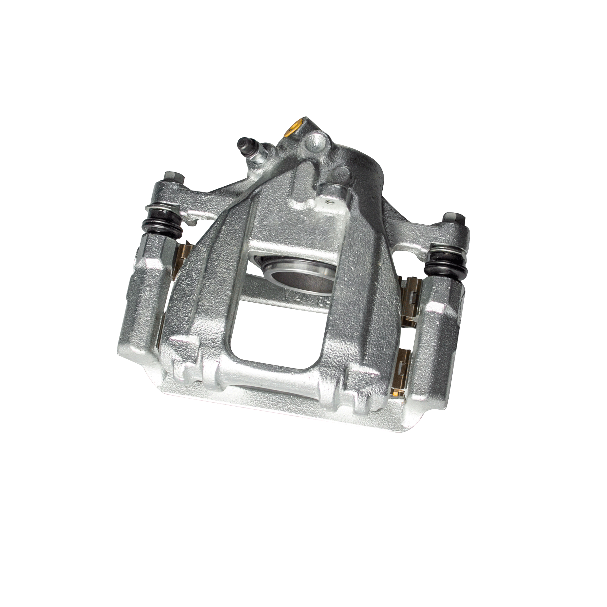
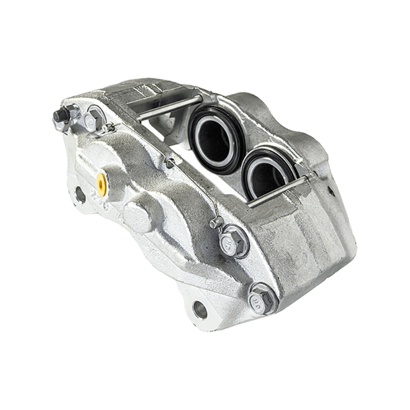
| Caliper and Piston | Straddling the rotor | Clamps pads against the rotor face |
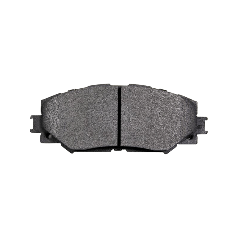
| Brake Pads | Inside the caliper | Friction surface against the rotor |
| Rotor or Disc | Mounted on the wheel hub | Rotating surface that absorbs friction heat |
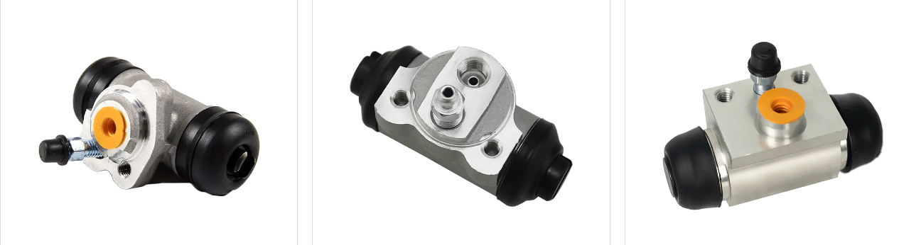
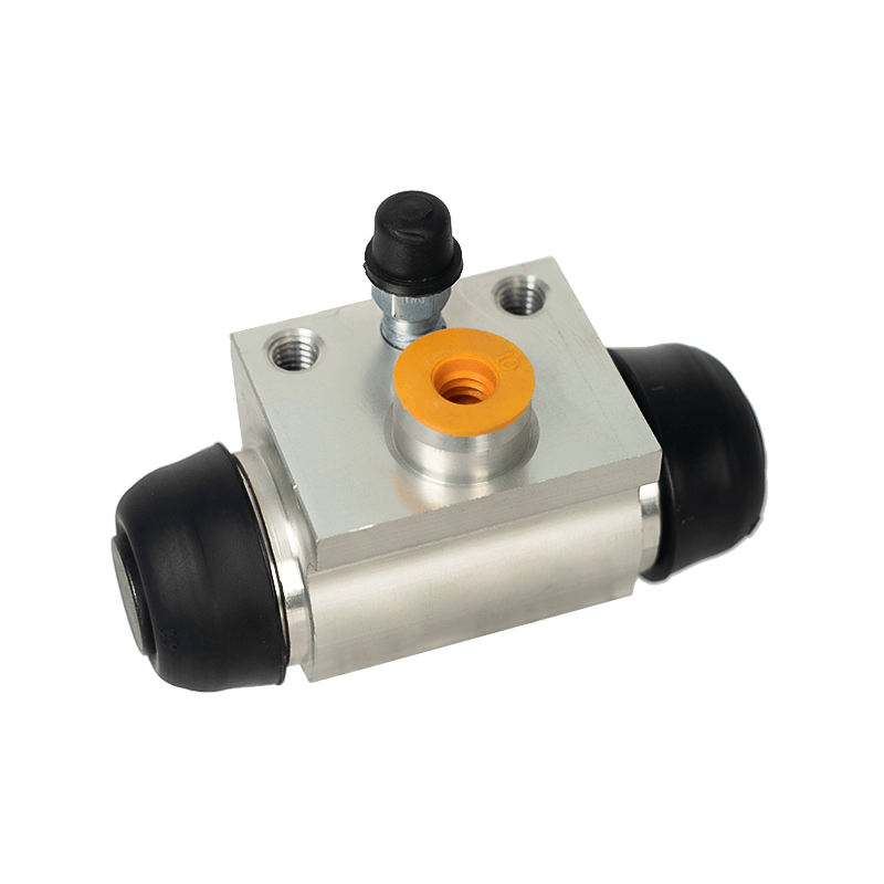
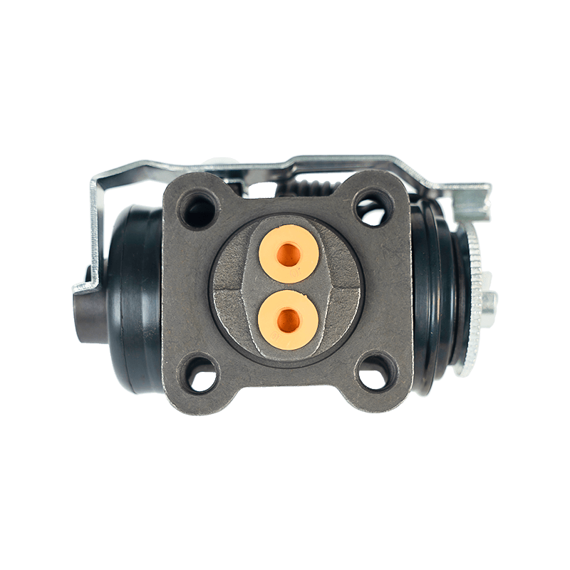
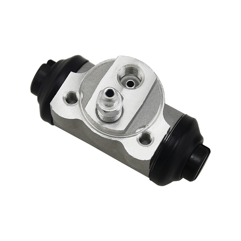
| Wheel Cylinder | Inside the drum assembly | Pushes shoes outward against the drum |
| Brake Shoes and Drum | Rear axle on many models | Enclosed friction assembly for the rear wheels |
| Parking Brake Mechanism | Rear wheels or driveshaft | Holds the vehicle stationary without hydraulic pressure |
| Wheel Speed Sensor | Near the hub bearing | Feeds rotation data to the anti-lock control unit |
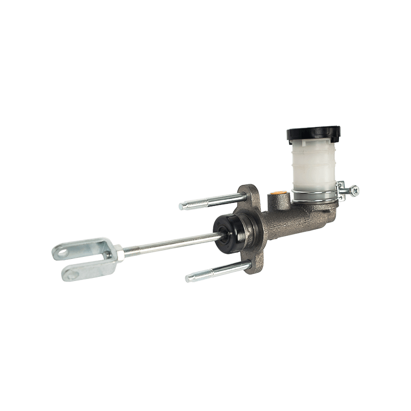
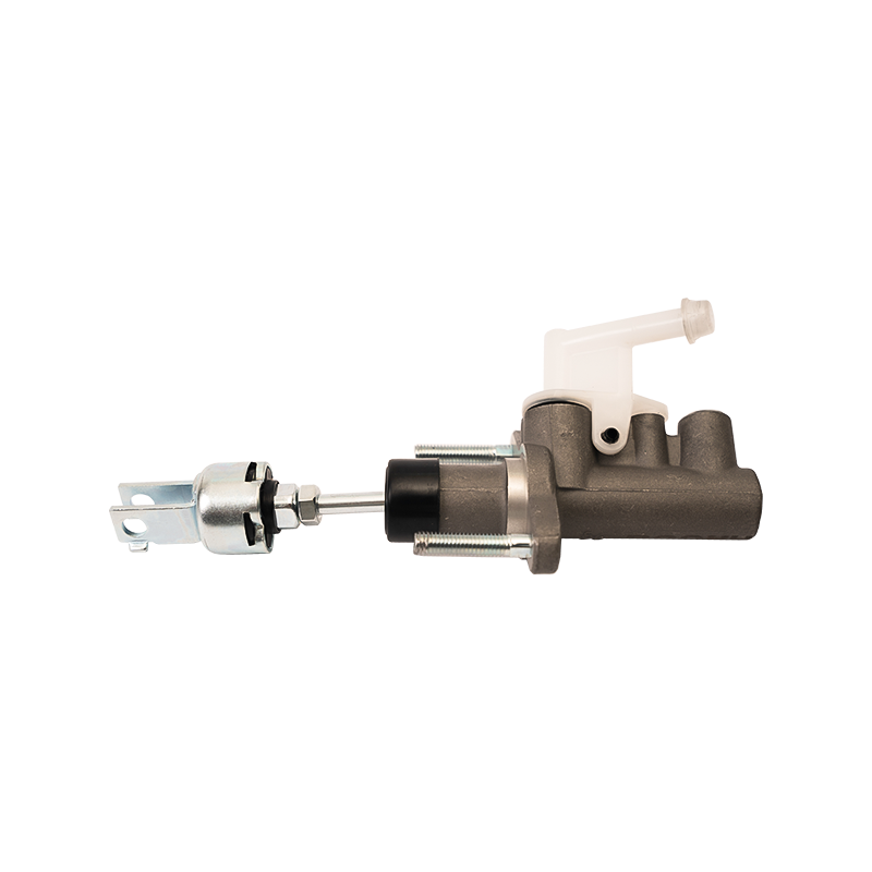
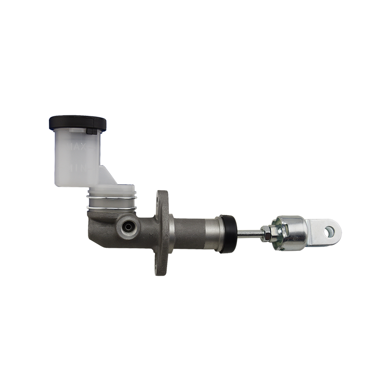
Clutch related hydraulic parts, including the clutch master cylinder and clutch slave cylinder, share the same fluid principles as the brake hydraulic circuit even though they act on the transmission rather than the wheels. Buyers who source both brake and clutch hydraulic parts from a single automotive brake system manufacturer often find it easier to match seal compounds, bore sizes, and fluid specifications across the two systems.
How a Hydraulic Brake System Works
Nearly every passenger car and light commercial vehicle on the road uses a hydraulic brake system rather than a purely mechanical one, because hydraulic fluid transmits force evenly and almost instantly to every wheel. The sequence below outlines the operating cycle from the moment the pedal is pressed to the moment the wheel slows down.
- The driver presses the brake pedal, and the booster amplifies that mechanical input.
- The master cylinder converts the amplified force into hydraulic pressure inside the brake fluid.
- Pressure travels through the brake lines and hoses to each wheel with almost no loss.
- At the front wheels, caliper pistons push the pads against the rotor face.
- At the rear wheels, caliper pistons or wheel cylinders push shoes outward against a drum.
- Friction between the pads or shoes and the rotating surface converts motion into heat, and the wheel slows.
- When the pedal is released, return springs and seals pull the pistons back and fluid returns toward the master cylinder.
Because the fluid circuit is sealed, any air pocket or moisture inside the lines compresses instead of transmitting force, which is one reason a spongy pedal usually signals that a hydraulic brake system needs bleeding or a fluid change. The chart below shows, on a relative index rather than an absolute unit, how a modest pedal input is progressively multiplied into a much larger clamping force by the time it reaches the caliper.
Illustrative force progression through a hydraulic brake circuit, values are a relative index and not measured units
Comparing Disc and Drum Automotive Brake Systems
Most automotive brake system layouts use disc brakes on the front axle and either disc or drum brakes on the rear axle. Disc brakes expose the rotor to open air, so they typically shed heat faster and hold their performance better under repeated hard braking. Drum brakes enclose the friction surface, which usually makes the parking brake integration simpler and can keep the assembly quieter at low speed, though the enclosed design manages heat less efficiently during sustained braking. The radar comparison below plots both layouts across six practical attributes on a one to five scale.
Disc brake layout Drum brake layout, scored one to five on each attribute
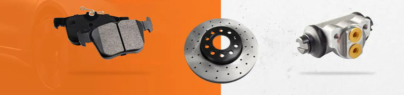
Neither layout is universally better, the right choice depends on axle load, vehicle segment, and how the parking brake is meant to work. This is why many automotive brake system manufacturer catalogs still carry both disc calipers and drum hardware side by side rather than phasing one out entirely.
Brake System Demand Across Vehicle Segments
Rotor diameter, caliper piston count, and pad compound generally scale with vehicle weight and intended use. Heavier platforms and vehicles that carry or tow loads place more sustained demand on the automobile brake system than a light passenger sedan does. The column chart below presents a relative demand index across four common vehicle segments, sedans set as the baseline at one hundred.
Relative brake system demand index by vehicle segment, sedans indexed at one hundred
Light commercial vehicles show the highest relative demand mainly because loaded weight varies widely between an empty run and a full cargo run, which asks more of the friction material and the cooling behavior of the rotor. Performance oriented vehicles show a lower index here only because the sample reflects everyday driving demand rather than track use, where their requirements rise sharply.
Brake Component Wear and Service Life Patterns
Brake pad thickness declines in a fairly predictable pattern under normal city and highway driving, though climate, terrain, and driving style all shift the curve. The line chart below illustrates a typical wear pattern from a fresh pad down to a thickness where replacement is usually due.
Typical remaining pad thickness against mileage under mixed city and highway use
| Factor | Effect on Wear Rate |
|---|---|
| Frequent stop and go city driving | Faster wear from repeated low speed stops |
| Steady highway cruising | Slower wear with fewer full stops |
| Mountain or hill descents | Faster wear and added heat exposure |
| Loaded or towing conditions | Faster wear from higher kinetic energy per stop |
| Coastal or high humidity climate | Faster corrosion related wear on hardware |
Choosing a Reliable Brake System Supplier and OEM Partner
Buyers evaluating a brake parts manufacturer or an automobile brake system supplier generally weigh a handful of practical priorities before placing an order. Dimensional accuracy and fitment consistency tend to matter most, since a caliper bracket or master cylinder bore that is even slightly off specification can affect pedal feel or cause premature seal wear. The horizontal bar chart below ranks common evaluation priorities on a relative importance index.
Relative importance index for common brake supplier evaluation criteria
Beyond dimensional accuracy, buyers sourcing OEM brake parts generally look for a wide vehicle coverage range so that one automotive brake system manufacturer can support several platforms rather than a single model. Packaging that protects rotors and calipers during long distance shipping, along with clear labeling for European, American, Russian, Japanese and Korean vehicle applications, also reduces sorting errors once parts arrive at a regional warehouse.
- Confirm whether the supplier can support both brake and clutch hydraulic parts, which simplifies purchasing for workshops that service both systems.
- Ask for the breadth of the model range, since a catalog spanning thousands of part numbers usually signals broader vehicle coverage.
- Review how quickly a supplier can respond to custom part requests for less common vehicle applications.
- Check whether packaging and labeling are suited for the destination market rather than a single generic standard.
OEM Automotive Brake System Manufacturing at Scale
Yancheng Yanitiger Auto Parts Co., Limited works as a brake and clutch parts manufacturer, producing brake master cylinders, brake slave cylinders, clutch master cylinders, clutch slave cylinders, calipers, and brake pads across a wide model range. The catalog covers more than three thousand product models and over one thousand brake shoe and pad variants built for European, American, Russian, Japanese and Korean vehicle applications, which supports buyers who need a single automotive brake system manufacturer for several regional platforms at once.
| Manufacturing scale indicators for the brake and clutch product range | ||
| Years of Auto Parts Experience | Product Categories | Export Countries |
| 20 | 3000+ | 30+ |
The production line uses a domestic drum and roller line built around Japanese Panasonic technology, paired with an SAP integrated order scheduling system and a supplier collaboration platform. This setup lets a small batch order for a less common vehicle application run alongside larger production batches without disrupting either schedule, which matters for buyers who need both OEM automobile brake system programs and aftermarket replacement parts from the same source.
Regional Vehicle Compatibility for Brake Parts
Brake configuration tends to follow regional vehicle design habits as much as it follows raw vehicle weight. The table below summarizes general patterns across five major regional vehicle groups.
| Regional Vehicle Group | Common Vehicle Types | Brake Configuration Notes |
|---|---|---|
| European | Compact and mid-size passenger cars | Front disc paired with disc or drum rear depending on trim |
| American | Full-size sedans, pickups and SUVs | Larger rotors and multi-piston calipers on heavier platforms |
| Japanese | Compact and mid-size sedans and hatchbacks | Lightweight rotor and caliper packages |
| Korean | Compact to mid-size cars and crossovers | Similar layout to Japanese platforms with model specific mounting |
| Russian | Light trucks and cold-climate passenger models | Components specified for wider temperature tolerance and corrosion exposure |
Maintenance Practices That Extend Brake System Life
A handful of routine habits go a long way toward keeping an automobile brake system working consistently between major services.
- Inspect pad and shoe thickness at regular service intervals rather than waiting for a warning noise to appear.
- Check brake fluid level and color, since darkened fluid often signals moisture contamination.
- Have the hydraulic circuit bled on a schedule suited to the vehicle and local climate.
- Inspect rotors and drums for scoring, heat spotting or uneven wear during routine service.
- Confirm caliper slide pins and wheel cylinders move freely to prevent uneven pad contact.
- Adjust and test the parking brake mechanism so it holds without excessive lever or pedal travel.
- Avoid prolonged light dragging of the pedal on long descents, and use a lower gear to help manage speed instead.
Common Causes of Brake System Failure
Most brake system failures trace back to a handful of recurring causes, each with a fairly recognizable symptom.
| Cause | Typical Symptom | Contributing Factor |
|---|---|---|
| Fluid contamination or moisture | Spongy or sinking pedal | Extended intervals between fluid changes |
| Worn friction material | Squealing or grinding noise | High mileage without inspection |
| Warped or scored rotor | Pulsation felt through the pedal | Repeated heat cycling from hard stops |
| Caliper or wheel cylinder seizure | Vehicle pulls to one side | Corrosion or lack of lubrication on slide pins |
| Air trapped in the lines | Soft, inconsistent pedal feel | Improper bleeding after service |
| Brake fade | Reduced stopping power on long descents | Sustained heat beyond the friction material working range |
Frequently Asked Questions About Automotive Brake Systems
Q1: What is an automobile brake systemIt is the complete set of parts, hydraulic, mechanical and electronic, that slows a vehicle or holds it stationary by converting motion into heat through friction. |
Q2: How does a hydraulic brake system workPedal force is amplified by a booster, converted to fluid pressure at the master cylinder, and carried through sealed lines to push pads or shoes against a rotor or drum. |
Q3: What are the four types of braking systemsDisc brakes, drum brakes, parking or emergency brakes, and regenerative braking used alongside friction brakes on hybrid and electric vehicles. |
Q4: What are the main parts of a brake systemMaster cylinder, booster, lines and hoses, calipers or wheel cylinders, pads or shoes, rotors or drums, and the parking brake mechanism. |
Q5: How long do brake systems lastPads and shoes commonly need replacement well before hydraulic parts do, and service life varies widely with driving style, terrain and climate. |
Q6: What causes brake failureFluid contamination, worn friction material, trapped air in the lines, seized calipers, and sustained heat beyond the friction material working range. |
Q7: How do you maintain a brake systemInspect pad thickness regularly, monitor fluid condition, bleed the lines on schedule, and check that calipers and the parking brake move and hold correctly. |
Q8: What is the difference between ABS and conventional brakesABS uses wheel speed sensors to modulate pressure and prevent wheel lockup during hard braking, while a conventional system applies pressure without that automatic adjustment. |

CONTACT INFOR.
-
 +86-152 5110 1941
-
 Info@yanitiger.com
-
 +86-152 5110 1941
-
 Building 5, Yancheng Financial City, No. 5 Century Avenue, Yancheng City, Jiangsu Province, China
Copyright © Yancheng Yanitiger Auto Parts Co., Limited All Rights Reserved. Custom Automobile Brake Products Factory OEM Automobile Brake Products Manufacturers
